-
Notifications
You must be signed in to change notification settings - Fork 2
User_Guide
Table of contents generated with markdown-toc
These instructions describe how to set-up and run an autonomous waypoint mission using Propbot. If you are not executing the mission in simulation, skip the instructions for Setting up the simulation computer.
In order to set up the mission command centre to communicate with the vehicle autonomy computer, perform the following steps:
- Make sure both the mission command centre computer and vehicle autonomy computer are on the same network. Do a simple ping test to make sure they can communicate with each other.
- On the vehicle autonomy computer, run:
export ROS_MASTER_URI=http://vehicle_autonomy_computer:11311. - On the vehicle autonomy computer, run:
roscore. - On the mission command centre computer, run:
export ROS_MASTER_URI=http://vehicle_autonomy_computer:11311.
Make sure the export command is either in run in every terminal used.
Repeat steps all of the above steps to set up communication between the simulation computer and vehicle autonomy computer.
On the simulation computer, build all of the packages inside the simulation directory.
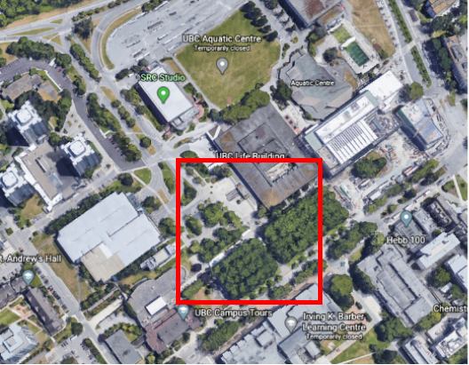
catkin build propbot_gazebo propbot_rviz propbot_simulationThe following commands will a launch simulation environment that is modeled off of this area on UBC campus.

If you would like use a static simulation environment launch the following file:
roslaunch propbot_simulation ubc_student_union_sim.launchIf you would like to use a dynamic simulation environment launch this file instead of the one above:
roslaunch propbot_simulation ubc_student_union_sim_people.launchBuild all of the packages inside the vehicle_autonomy and common directory:
catkin build propbot_autonomy propbot_control propbot_description propbot_drivers propbot_mission propbot_navigation propbot_slam propbot_state_estimation propbot_common_msgs propbot_utilLaunch the autonomy stack:
roslaunch propbot_autonomy autonomy.launchBuild all of the packages inside the mission_command_centre and common directory:
catkin build mapviz_plugins propbot_mission_gui propbot_common_msgs propbot_utilLaunch the mission command centre GUI:
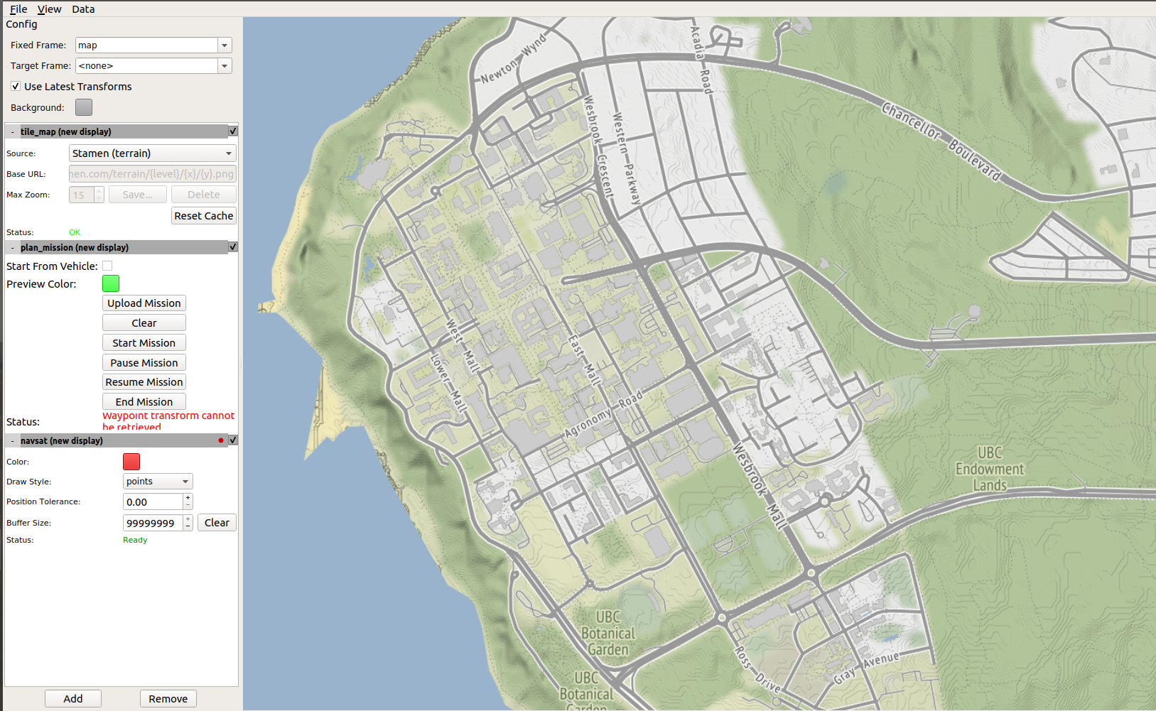
roslaunch propbot_mission_gui mapviz.launch
The above shows the default GUI configuration. If you would like to display satellite map tiles follow the instructions from this repository
ROS Offline Google Maps for MapViz: https://github.com/danielsnider/MapViz-Tile-Map-Google-Maps-Satellite
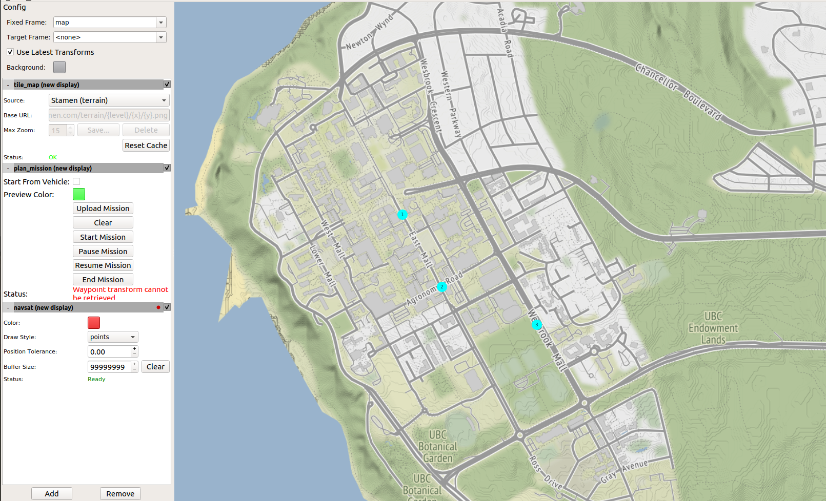
Configure and command a mission using the plan_mission section of the control panel:
- Select mission waypoints by clicking on the map and clear them as you like by selecting Clear
- Once you are satisfied with your mission configuration, upload the mission to propbot by selecting Upload Mission
- Start the mission by selecting Start Mission
- You may pause, resume, or end the mission at anytime by selecting Pause Mission, Resume Mission, and End Mission
- Monitor the robots progress on the display
Note: You must wait until a mission is finished or end the mission before uploading a new one

In order to set up the mission command centre to communicate with the vehicle autonomy computer, perform the following steps:
- Make sure both the mission command centre computer and vehicle autonomy computer are on the same network. Do a simple ping test to make sure they can communicate with each other.
- On the vehicle autonomy computer, run:
export ROS_MASTER_URI=http://propbot@vehicle_autonomy_computer:11311. - On the vehicle autonomy computer, run:
roscore. - On the mission command centre computer, run:
export ROS_MASTER_URI=http://propbot@vehicle_autonomy_computer:11311.
Make sure the export command is either in run in every terminal used.
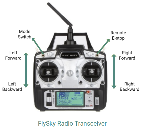
The FS-T6is a six-channel transmitter with two joysticks and four programmable switches. This provides a joystick foreach set of wheels and programmable switches for a remote kill switch and a autonomy to manual mode switch. The figure below demonstrates how the four functions mentioned above are distributed on the transmitter. The remote controller receiver is FS-R6B, which is a six-channel receiver.

The right and left joysticks control the right and left longitudinal sets of robot wheels, respectively. The user can choose between linear and non-linear speed mapping within the firmware to achieve varying speed resolutions.
The maximum speed of a robot can also be clamped by altering the maximum duty threshold in the firmware.
When switch B is high, the mode is set to autonomy in which the autonomy
computer can control the robot's movement. The low position indicates manual
mode.The switch works asynchronously and so the mode can be switched at any time.
Switch A controls the remote e-stopping functionality. When switch A is in the high position, the vehicle interface will send 0 speed commands and inputs from the movement joysticks are blocked. Once de-asserted, the speed commands return to following the movement joysticks.