-
Notifications
You must be signed in to change notification settings - Fork 123
Quick Start Guide
First you have to start Modelio by double-clicking on the Modelio shortcut.
Once Modelio is started, go to 'File / Create a project...' or click on the [ ] button. This will open a Project Creation dialog box:
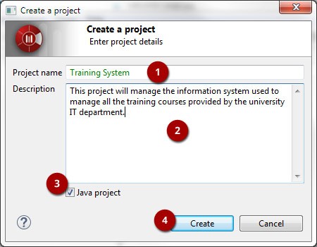
Steps:
- Enter a project name
- Enter a description
- You can choose to deploy the Java Designer module in your project by checking or not checking the Java project tickbox.
- Click on "Create"
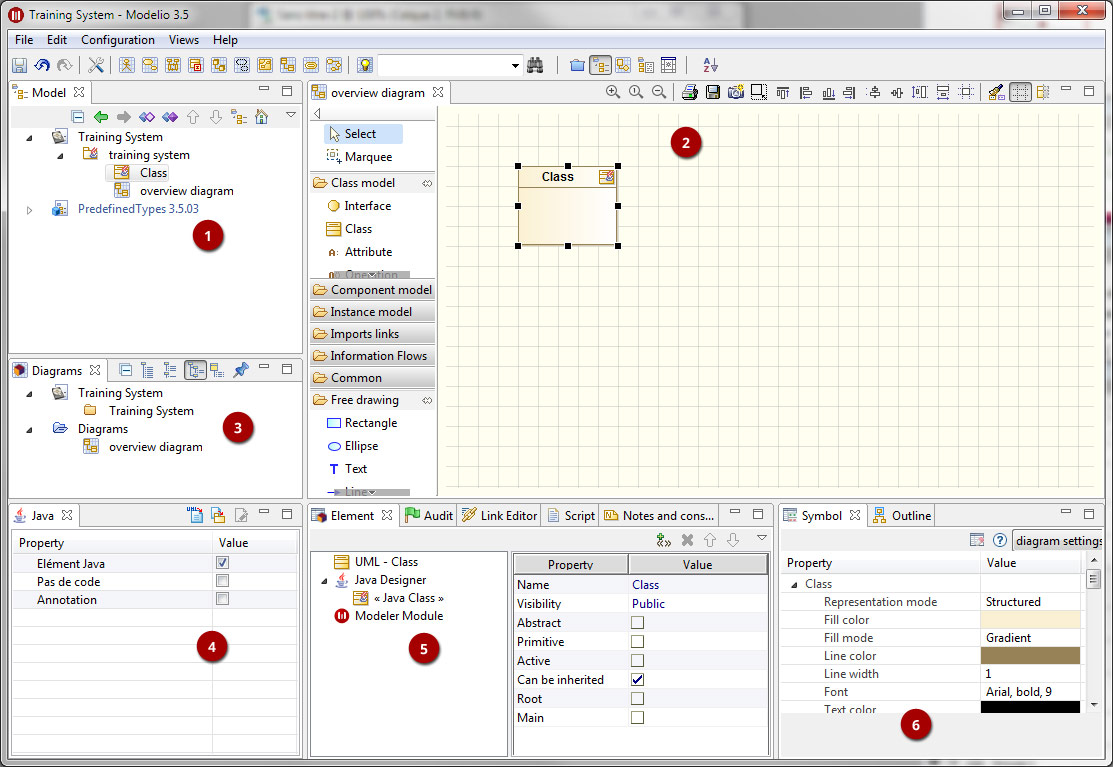
Key:
- Model explorer (UML, BPMN, MDA, Requirements, ...)
- Diagram view
- Diagrams explorer
- Module view
- Properties view
- Symbol view

Key:
- Save
- Undo/Redo
- Project Configurator: Project information, Work models, Libraries, Modules, Audit, URLs
- Quick diagram creation
- Diagram creation wizard
- Advanced search tool
- Perspectives: Change the layout of the views
- Sort model elements
From the diagram view
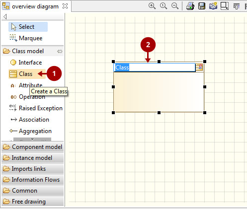
Key:
-
Choose the type of element you want to create from the diagram palette
-
Click in the diagram to position the new element. Click again on the element to rename it (or click on the F2 keyboard button)
From the UML model explorer
To create your first element, right-click on the root package and then on 'Create element'. Choose the kind of UML/BPMN element you want to create:
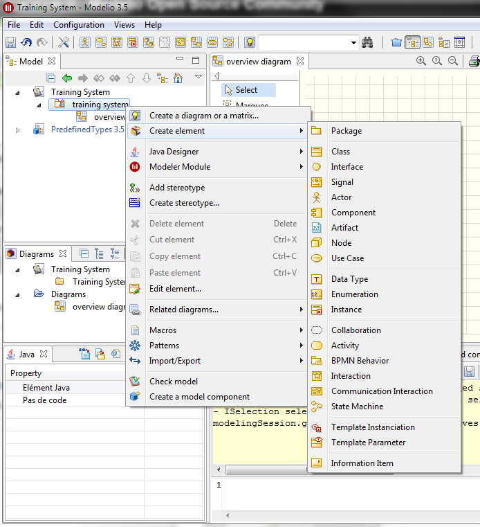
Sibling creation
To create a series of elements, simply select the original element in the model explorer, then click on sibling button as many times as necessary. Each new element will be created empty and named with an incremental number. Sibling elements are created within the same container.
Clone creation
To clone an element, simply select it in the UML/BPMN explorer, then click on clone button as many times as necessary. Each new element will be created with the same sub-elements as the original one, and will be named the same.
** Diagram creation** Click on the Diagram and matrix creation wizard icon in the main toolbar:
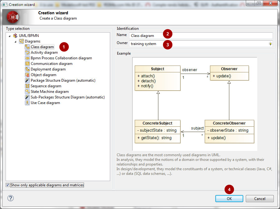
Steps:
-
Select the kind of diagram you want to create
-
Enter a name
-
Select an owner for the diagram
-
Click on "OK" to create the diagram
Note: By default, the wizard shows the applicable diagrams for the selected model element. Click on the "Show only applicable diagrams and matrices" to show all existing diagrams.
Create elements in the diagram
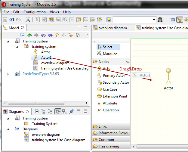
To create elements in your diagram, you can either use the left hand side palette, or drag&drop existing elements from the UML explorer.
Modify the graphic options
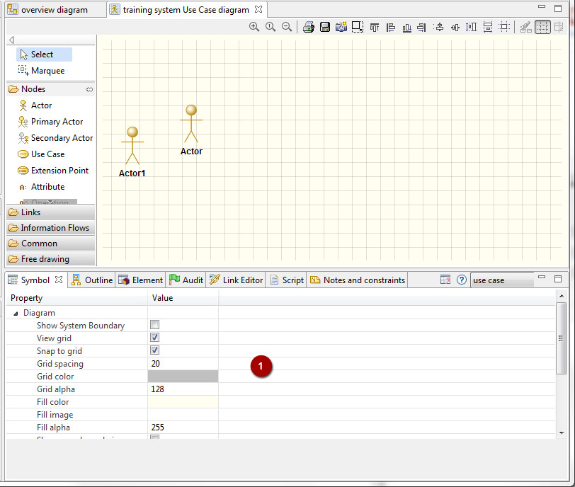
You can change the objects' graphic properties or the diagram's properties itself. The symbol view offers several options to change the graphic properties: color, font, line background, ...
Key:
- Change the options in the Symbol view
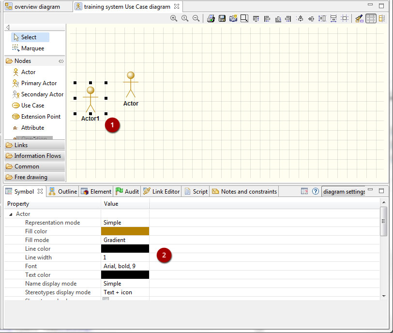
Change objects' graphic properties
Key:
-
Select a graphic element
-
Change the options in the Symbol view