-
Notifications
You must be signed in to change notification settings - Fork 3
03.Assembling
Make sure you have all the parts listed on the previous page.
These are the first two items to install in the palm.
You need two M3x12 screws, nuts and washers.
Insert one nut in the slot (1) of the low pulley.
Make sure to put a washer between the pulleys and their plastic supports (2 and 3) so that the pulley will not be pressed against the plastic when you tighten the screw.
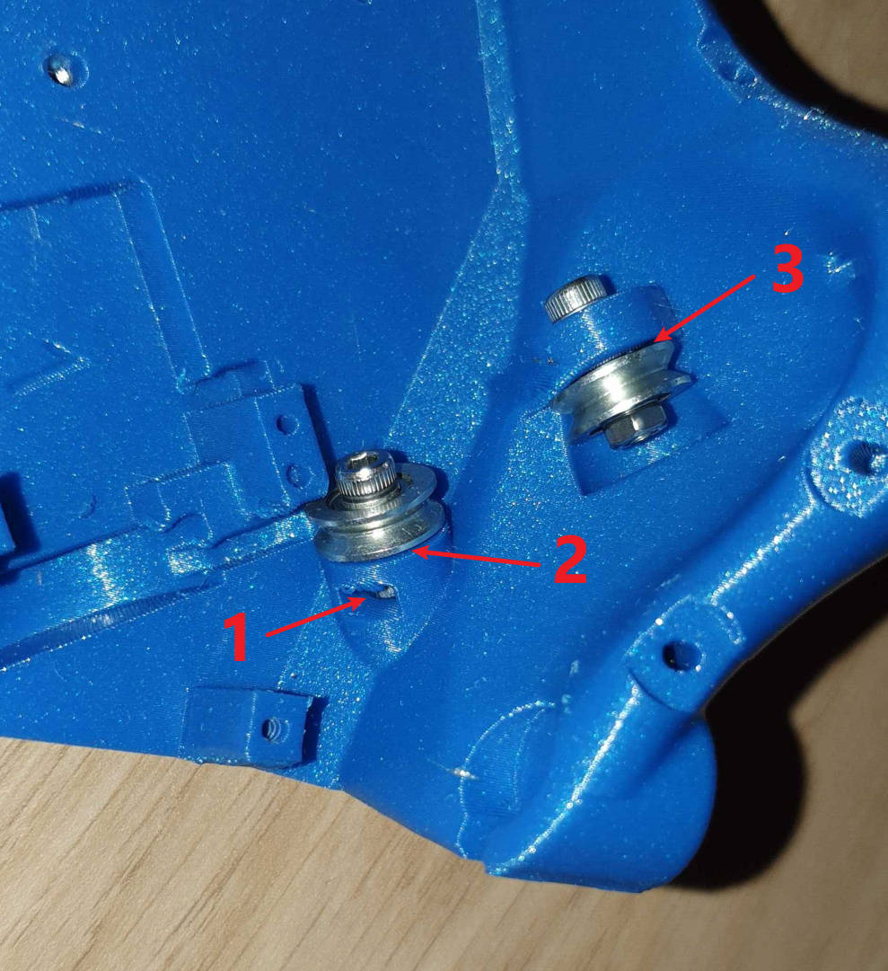
First, place 3 M3 nuts in their slots in the palm. They should be pushed in with the flats running along the channel with the point of the hex going in first (Thanks Connie!). It's not too easy to you can help yourself by printing the nutTool.stl file that will help push the nuts with the correct orientation.
Make sure to push them all the way and align them to the holes in the palm.

Then place the servo platform in the palm, and screw in the 3 M3x12 screws to secure it in place. Tighten slightly.

For the 3D parts, thumb is 1, index is 2, and so on (beware if you modify the software, thumb is 0, etc.)
Each part has the finger number engraved.

These markings are also present on the hand and platform to place the right servos with the right pulleys, on the servo covers, and on the PCB terminals to correctly plug the servo to the appropriate terminal.

Before assembling the finger parts, make sure to clear the wire holes using a hand drill and a thin drill bit:

All the way through!

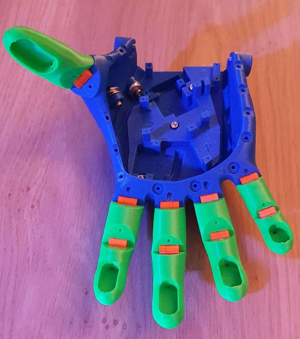
The knuckles join the two part of each finger, and then the finger bases to the palm.
Contrary to the original Kinetic hand, the Kinetix is not using TPU printed knuckles, because they put some strain on the servo motors which, being small, have then no strength left to hold anything.
Instead, I've replaced them with print in place hinges which require no effort to bend, but which won't unfold the finger like the TPU ones were doing. This is achieved by pulling a wire on top of each finger when the motor turns in reverse.
Knuckle sizes required for each finger:
- Thumb (1): 1.1
- Index (2): 1.1 and 1
- Middle finger (3): 1.1 and 1.1
- Ring finger (4): 1 and 1
- Little finger (5): 1 and 0.9
Refer to the knuckle sizes above to assemble the fingers parts, and the palm.
You can try to fold the knuckles before inserting them in the fingers, but do not use pliers, you could damage them.
20240404_132333.mp4
If they can't be folded with your bare hands, do it once they are inserted in their slots, and they should fold with a snap rather easily. Make sure to fold according to the axis, not sideways.
20240401_161008.mp4

Make sure to push the knuckles all the way into their slots so that their axis is aligned with the base of the cut in the finger.

Once you have put together the palm, fingers and knuckles, you will probably need to manually fold and unfold the fingers a few (or many) times until they move freely, in order to not put strain on the servo motors.
A good test is to rotate the palm up and down and check gravity is enough to fold and unfold the fingers.
You may notice that even pushed all the way in, the thumb knuckle remains a bit out of its palm slot, it's all right.

Et voilà! :

The motors use double pulleys with different diameters, because the wires to fold the fingers and the ones to unfold the fingers do not have the same course. The courses also varies from one finger to the next, which is why each finger has its own double pulley, they should not be mixed up, so they have the finger number engraved on them.
The servos used in this project have a 0 to 180° course.
Before mounting a pulley on a servo, the servo needs to be driven to "position zero", which is the servo position for the finger completely open.
Because of the relative position of servos, fingers 3 and 5 (5 being the little finger) have a "position zero" opposite to the 3 others, their "position zero" will actually be 18O°.
So once you have positioned them, you need to remember which servo will drive which finger. Put a small label on each with the finger number.
BEWARE: This is a feature in the firmware that should only be used when none of the servos are actually wired to the fingers, otherwise there is a risk to break something.
The board has "fingerX" labels. Be careful with the polarity (the next version of the PCB will have labels for + (red wire), - (black wire), and PWM (orange wire).
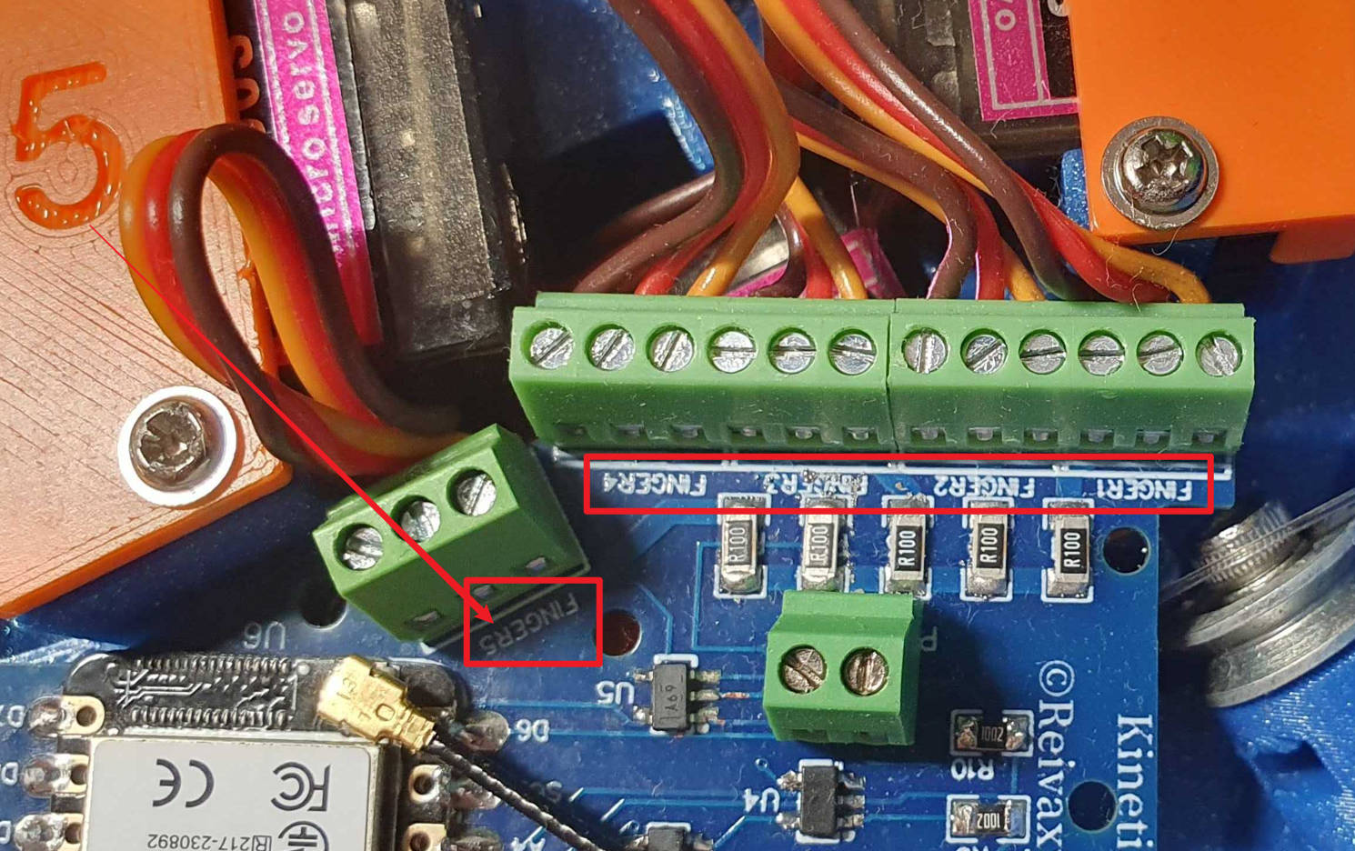
Next PCB version:

Do not put the servos in their brackets just yet, since we need to attach their pulleys first.
Check the polarity again (you could destroy a servo if not wired correctly).
If the firmware is already uploaded to the ESP32, the servos will move for about 3 seconds during the initialization sequence.
If it is not, please check the page about the firmware.
Launch the Android application on your phone.
If you never connected before, open the menu, select the "Devices" option. Select the "Kinetix" device. Tap the back button to go back to the main screen.
Tap the Connect button (if you didn't disable voice recognition, you may also just say "connect").
Once connected to your device, open the menu, select the "Tools" activity, then tap the button "Calibration".
When you confirm the Calibration, the servos will all alternate between the fully "open" and full "closed" positions.
But they stay in the "open" position for 5 seconds, and in the close position for 1.5 second, so you easily can tell when they are in the "open" position.
Unplug the power while they are in the open position.
Once the servos are calibrated, disconnect them from the connectors.
BEWARE: in the next steps, be careful to not move the servos from this position, especially when attaching the pulleys.
Also make sure to not switch the servos, they don't all have the same default position.
Each pulley should be equipped with one piece of wire, held in place by one crimp bead:
Cut a 40 cm piece of wire. Set a crimp bead right in the center and squash it with pliers. Not too hard, but hard enough :)


Then thread it through the pulley holes so that the crimp bead is inside the pulley and both wire ends come out the groove holes.
First drive it through the pulley, and make sure the bead is inside near the middle
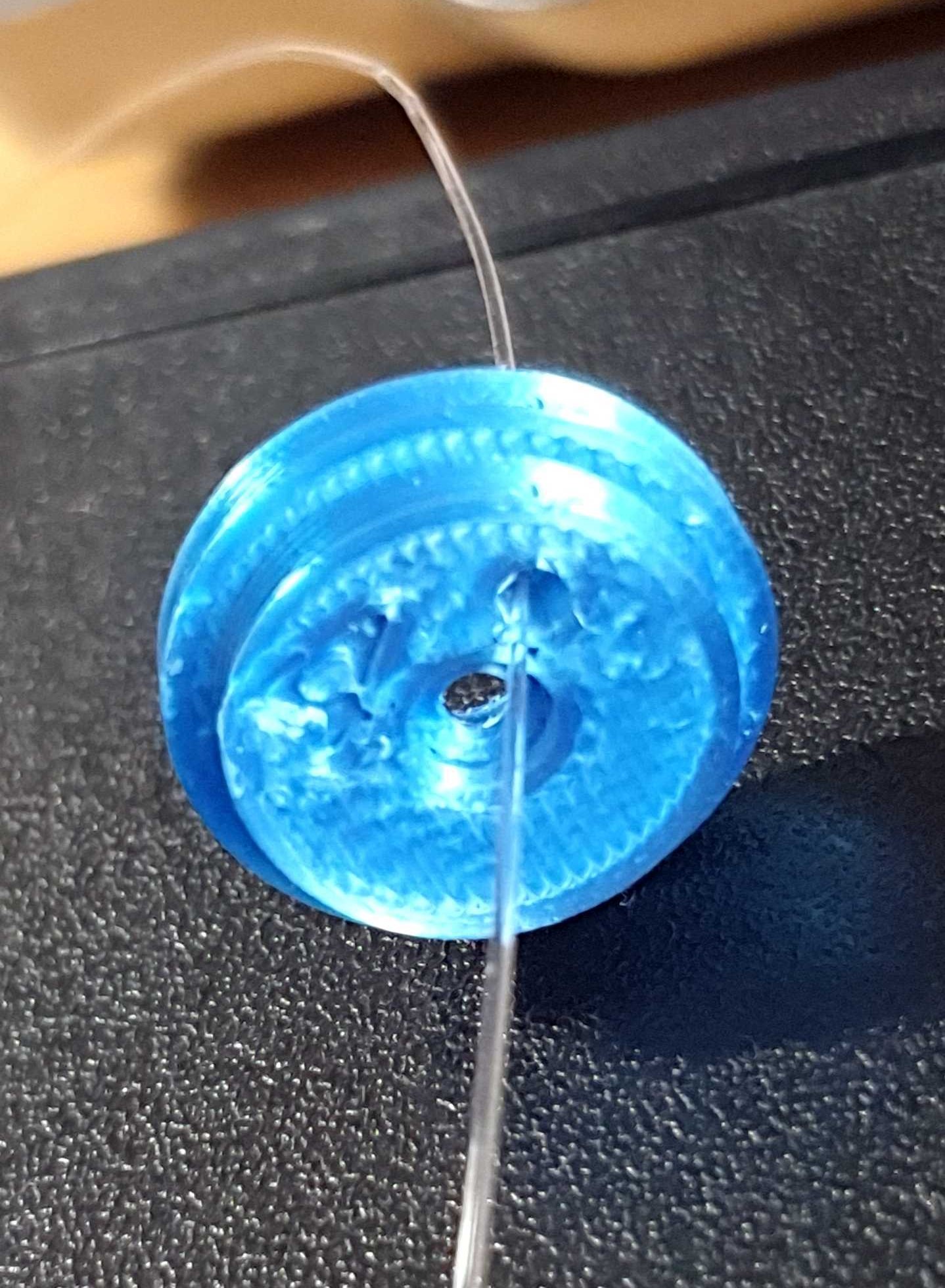
Then push each wire extremity back in its hole then up through its groove hole
I'm not great at drawing, but let's say the bead is purple and the wire is blue, here is how you do it:

Then pull each wire extremity, until the bead is inside the pulley and both wire extremities through the grove holes.

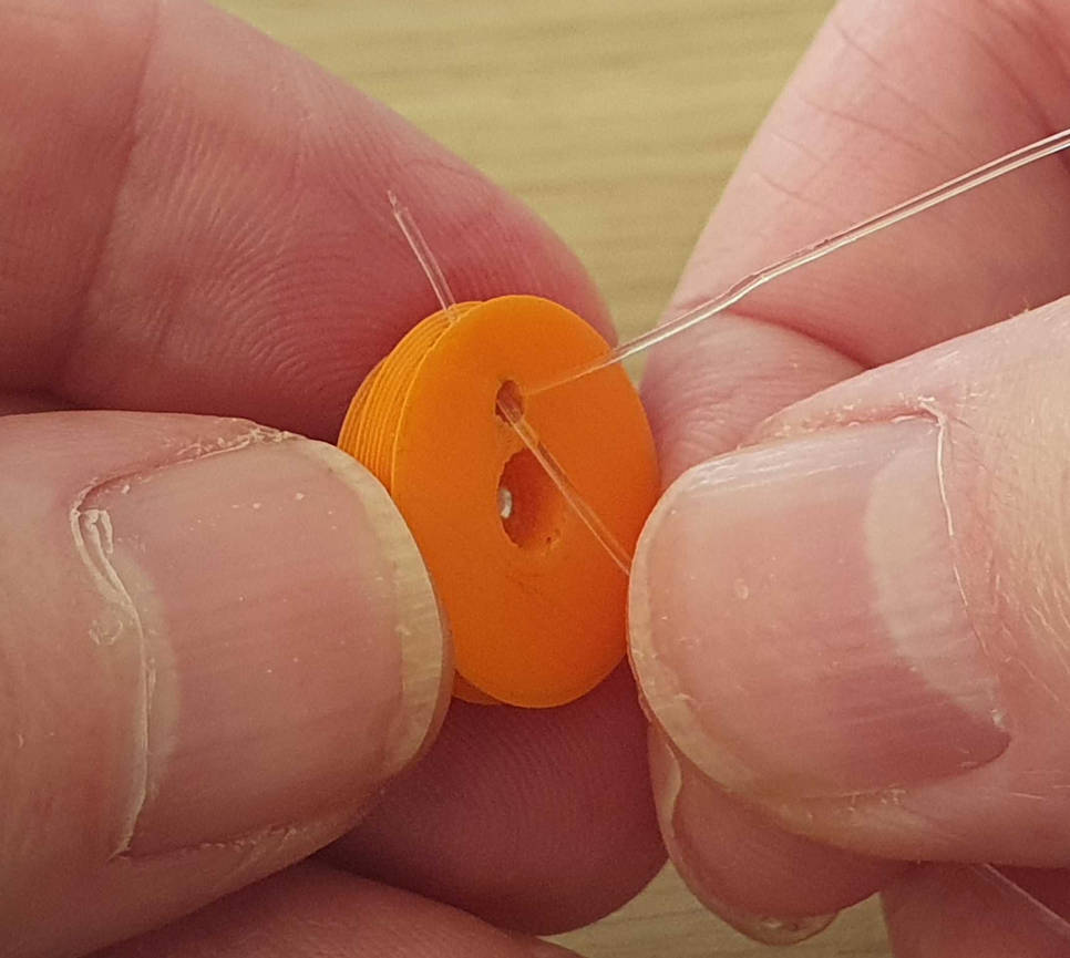

And here is the result (although the pulley should not change color).

Before attaching a pulley to a servo, check the servo position in the hand. They shouldn't be mixed up, and you need to know the top side of the servo from its bottom side
Now, push the pulley on the servo axle with the wires emerging on top relative to the servo position in the hand. This is very important because you must not rotate the servo axle by hand, you must set it in the correct position.
Make sure the axle does not rotate so that it keeps its position from the calibration phase.
FOR A RIGHT HAND: this is what the servo + pulley + wire should look like for the thumb
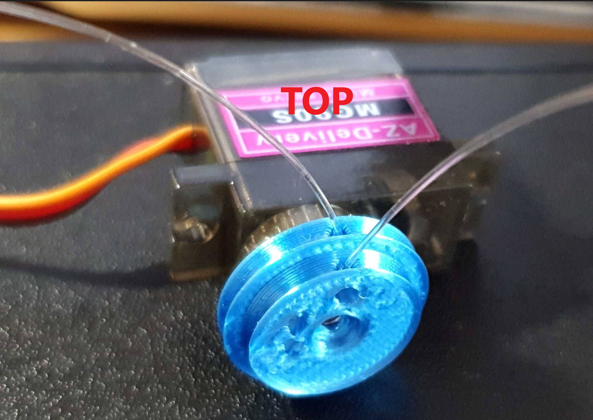
FOR A RIGHT HAND: this is how they should like for the other fingers:

FOR A LEFT HAND, IT'S THE OPPOSITE.
Use the axle screws provided with the servos to secure each pulley on its servo.
Be careful to tightly block both the servo and the pulley with your fingers so that you feel if the pulley rotates independently of the servo axle. If it does you'll need to print a tighter pulley and will probably need to recalibrate the servo. To do that, unplug the already wired servos (the ones where the wires are already set and blocked in the fingers.)

Once the screw is tight, set the servo in its slot and secure it with the cover and the screws provided with the servo:

For all servos+pulleys: the wire on the larger side of the pulley is intended to fold the finger, so it will go inside the finger inner canal.
The wire on the smaller side of the pulley is intended to open the finger, so it will first go round the pulley, then to the outer canal for the finger, but you need not care about this before you are ready to crush beads to block wires.

Drive the wires through their respective canals in the fingers, then through the wire blocker that fits inside the top finger slot. The engraving showing the number should be seen, this ensures correct wire canal alignment.

Unlike shown in the picture, you should run both wires before you crush bead on any one of them, because it's easier when the blocker can be moved freely. Then slide a crimp bead on the wire.
Hold the wire between your thumb and index and block the rest of the printed hand with the remaining of your fingers, pull slightly on it, but make sure the pulley does not rotate.

BEWARE: before crushing the bead on the "external" wire (the one intended to unfold the finger), make sure it goes around its (smaller) pulley !!

With your other hand use pliers to crush the crimp bead and block the wire.


And repeat with the other wire
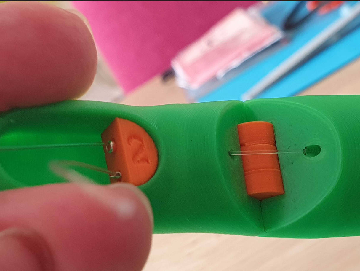
You should start with the pulley + servo for the thumb, because it's lower than the other ones and will be partially covered by the servo driving the little finger.
Set the servo in the palm, with the wires going up from the pulley.
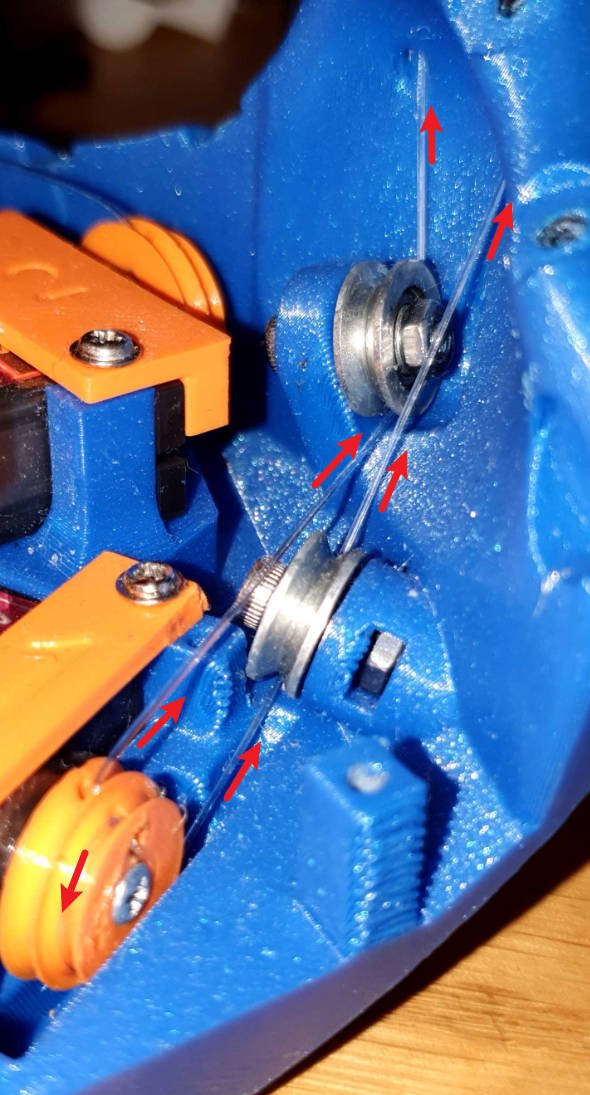
You will need to make the wires go through the metal pulleys:
