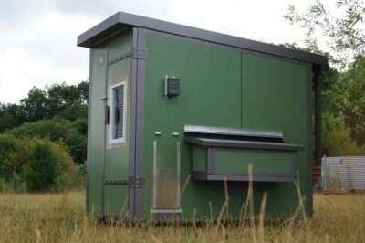
This is code for an ESP32-based Internet-of-Things (IoT) chicken door. We have a Heini Koop chicken coop, but the principle of this door mechanism is generic and should work with sliding and other doors.

The ESP is hooked up to a BME280 climate sensor (not needed, just for fun) as well as a BH1750 light sensor, as well as a DC motordriver connected to a 30 cm DC actuator to open and close the door. We currently have a ChickenGuard(TM) module to close and open the door. It works well, but lacks the Internet access. If you do not need the IoT functionality and do not want to tinker, go for the ChickenGuard(TM). If, say, you are away from home and decide that you want to let the chicken out manually tomorrow, but the door is in lux-mode (opens when a certain amount of daylight is reached) then you need to live with the situation. Furthermore, if you discover on your coop camera :) that one of the chicken didn't get in before the door closed automatically in the evening and you are not at home, you cannot open the door remotely to let the late-comer in. In our rural area, the likelihood is high that you then have one saturated predator more in the area and one chicken less. Last but not least, the standard ChickenGuard (TM) door can be simply pushed up once closed. They do have a model that locks, though, but we have the standard model. The DC actuator keeps the door closed once it is closed. No way to push it up. The downside of the actuator is that it is very powerful. If something gets in the way when the door closes, it or the door gets damaged.
Ok, so much for the motivation for this project. Here are the specs:
- 3 modes (manual-, time-based, light-based operation), independently selectable for opening and closing (e.g. open every morning at 8am, but close at night when the light is low).
- This obviously requires a light sensor. This one has a BH1750. You can also set a delay. If the light has been below or above threshold for a certain number of minutes, the door moves.
- BME280 for temperature, humidity and pressure
- Manual opening and closing with two buttons at the device.
- A INA219 current sensor that notices when the built-in end stops of the actuator have switched the device off, so the system knows when the door is fully open or closed.
- Web interface for the settings and sensor readings.
- Linear actuator with 30 cm range of operation, IP66 approved for outdoor application.
More todo here
Turns out that the ESP32 dev module can be picky with regard to which pins you can use for what. I tried around a bit and the following pins work for me:
- SDA 16
- SCL 17
- Motor_Pin_1 18
- Motor_Pin_2 19
- Button_1 26
- Button_2 27
I decided to build this device without a display and without the possiblity to adjust the settings directly at the device, apart from the two buttons to open and close the door. Instead, I added a web interface with a dashboard with two virtual buttons to open and close the door as well as some status information and sensor readings.
And there is a settings panel.
The mechanism was first setup on a piece of plywood so I could carry it around and test and develop wherever I wanted:
Here is the fritzing schema (yes, I am sure this can be done nicer :)):
The mounts that came with the actuator where useless as too short to mount the actuator for vertical operation, so I designed a mount in OpenSCAD and 3D printed it on my ender3. I eventually ordered the part in PA2020 (Nylon), 3D printed with Selective Laser Sintering (SLS), from RapidObject GMBH in Germany for maximum strength and durability.
And here is the final assembly working and in action:


