Will DO
- Teach how to setup the HRTIMer, its freq, PLL etc.
- Use the GPIO for timing and debugging
- How to setup period and duty cycle control
- Use RC circuit as a simulated SMPS circuits
- Observe "exactly" where in time the ADC is acquiring data
- Trigger the ADC by HRTIMer
- Interrupt by HRTIMer and/or ADC
- Check where exactly in time the acquisition of ADC by using single external resistor
Will not do
- Teach about the basic of SMPS, it theory, operations, formulas, etc
- Teach about feedback control theory
- Use actual Power devices to convert power
- Give overview of the evaluation board
This tutorial will use NUCLEO-F334R8 as the development board where the external Freq used is 8MHz, while the MCU has a maximum System Freq of 72MHz.
With 8Mhz input clock and Max 72Mhz of system freq, set the ff:
PLL = 8 (default and cannot change)
PLLMUL = 9
RCC_OscInitStruct.PLL.PLLMUL = RCC_PLL_MUL9;
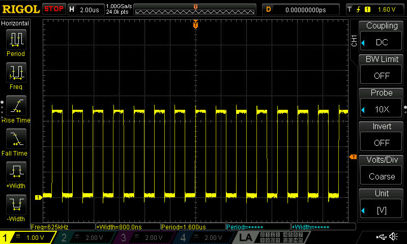
Check which code will yield the fastest GPIO speed, pls refer to GPIO Speed Test in STM32F334_HAL_LL_REG_GPIO
GPIO Set (HIGH) / Reset (LOW) in main while loop. Check the waveform:
HAL and LL Library
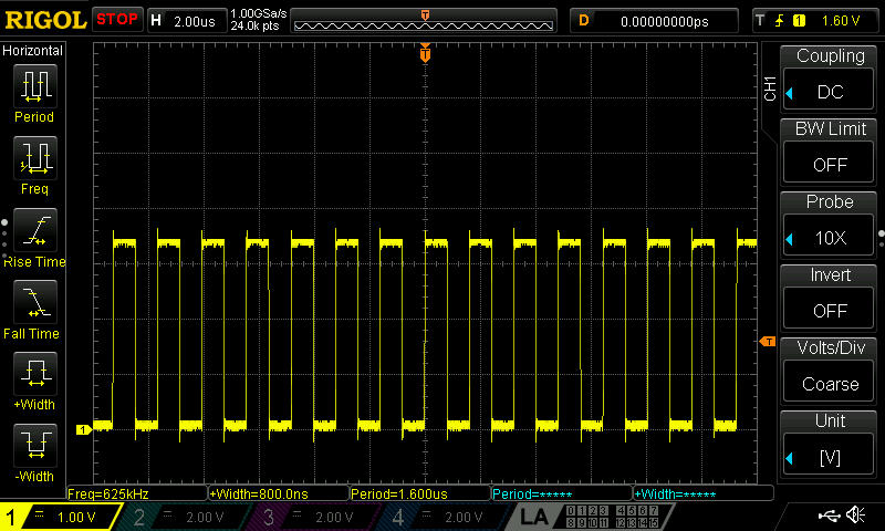
// HAL = 625 kHz
HAL_GPIO_TogglePin(GPIOC, GPIO_PIN_9);
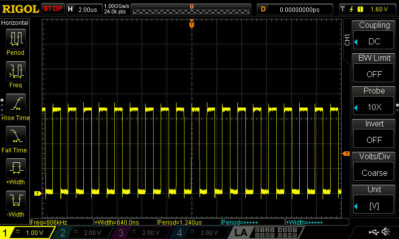
// HAL = 806 KHz
HAL_GPIO_WritePin(GPIOC, GPIO_PIN_9, GPIO_PIN_SET);
HAL_GPIO_WritePin(GPIOC, GPIO_PIN_9, GPIO_PIN_RESET);
// LL = 625 kHz
LL_GPIO_TogglePin(GPIOC, GPIO_PIN_9);
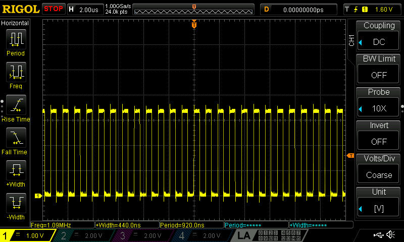
// LL = 1.09MHz
LL_GPIO_SetOutputPin(GPIOC, LL_GPIO_PIN_9);
LL_GPIO_ResetOutputPin(GPIOC, LL_GPIO_PIN_9);
Register Level Access
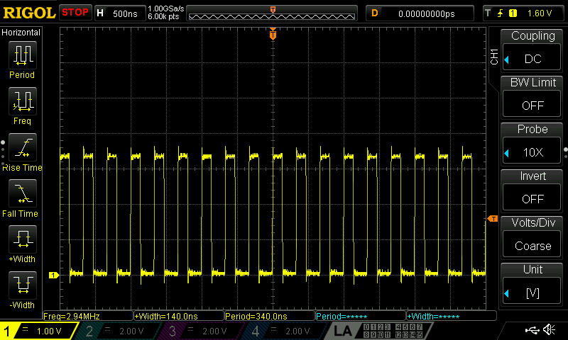
// HAL / LL  = 2.94Mhz
GPIOC->BSRR = (1 << 9); // Set
GPIOC->BSRR = (1 << 25); // Reset;

// HAL / LL  = 2.94Mhz
GPIOC->BSRR = (1 << 9); // Set
GPIOC->BRR = (1 << 9); // Reset;
As expected, toggle commands will take longer due to the fact, that it reads first before toggling. Also, using register level will be faster. So this code below will be used for setting HIGH and LOW the GPIO for debug use.
GPIOC->BSRR = (1 << 9); // Set
GPIOC->BRR = (1 << 9); // Reset;
Set PLL as source (with integrated multiplier of 2)
PeriphClkInit.Hrtim1ClockSelection = RCC_HRTIM1CLK_PLLCLK;
Set prescaler to multiplier of 32
pTimeBaseCfg.PrescalerRatio = HRTIM_PRESCALERRATIO_MUL32;
At this moment HRTIMer freq is running at 4.608Ghz or 217pS, 72MHz x 2 x 32. We mutiplied to this high freq to have a resolution of 217pS.
The period register in HRTIMer is 16bit register, that means it can count to 2^16 = 65536, theoretically. That is because some bits/byte combination are lost, so just nearly 65,536.
To operate at 100kHz (10us) switching freq, we need 46,080 clock cycles. It is with in the 65536 max counter limit.
If we exeed that couter, we will use a prescaler multiplier of 16 intead.
That means the period we have now is 46,080 x 217pS. When the counter reach 46,080, it would return to 0. It also means we have a duty cycle resolution of 1/46,080. That's 0.0217%!
pTimeBaseCfg.Period = 46080;
We will use Comparator1 and Comparator3, Comparator1 for the max duty cycle while Comparator3 for setting the duty cycle.
We set Comparator1 to be less 1000 of the duty cycle, for safety.
pCompareCfg.CompareValue = 46080 - 1000;
We set Comparator3 at the meantime 50%.
pCompareCfg.CompareValue = 46080/2;
For the GPIO output setting, we set HIGH the output when the HRTIMer readh the period and set LOW when it reach Comparator1 "OR" Comparator3.
pOutputCfg.SetSource = HRTIM_OUTPUTSET_TIMPER;
pOutputCfg.ResetSource = HRTIM_OUTPUTRESET_TIMCMP1|HRTIM_OUTPUTRESET_TIMCMP3;
Set the IO speed to slow, so we dont generate too much noise.
GPIO_InitStruct.Speed = GPIO_SPEED_FREQ_LOW;
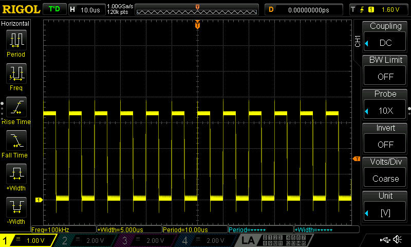
By Comparison, if the speed is "HIGH", see below noise on the output.
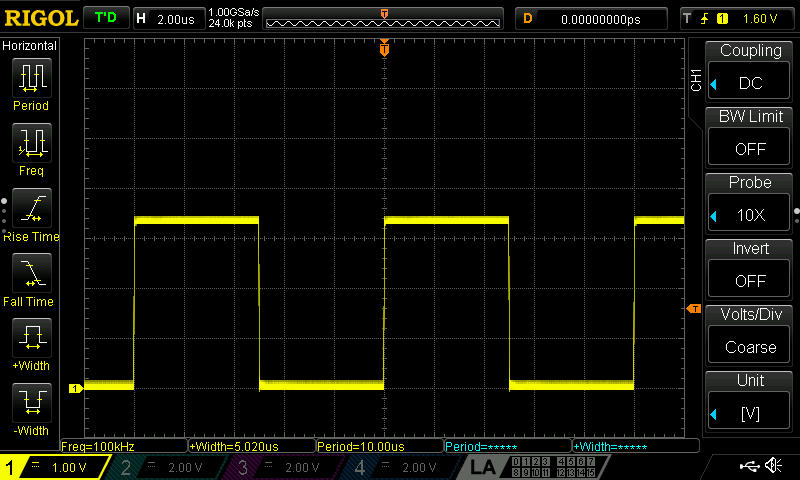
Here the speed is "LOW"
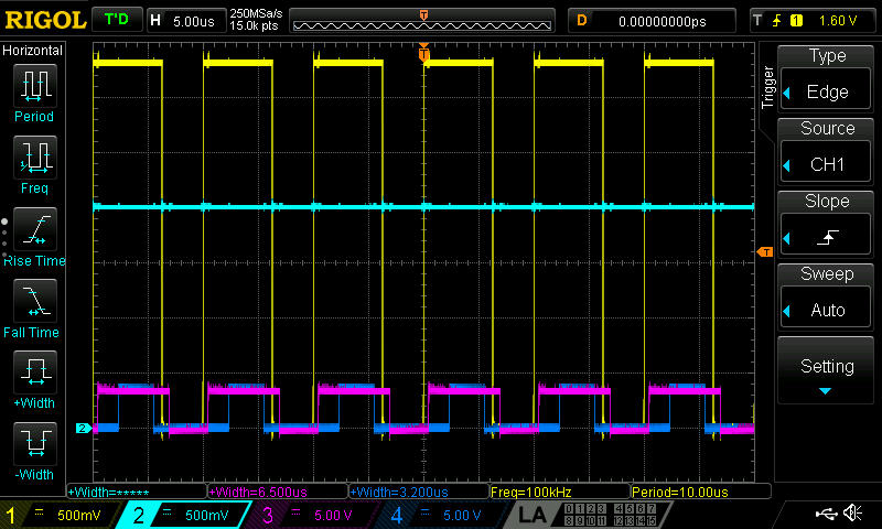
In the main.c we start the HRTIMer counter and enable its GPIO output. Check the output waveform.
HAL_HRTIM_WaveformOutputStart(&hhrtim1, HRTIM_OUTPUT_TE1);
HAL_HRTIM_WaveformCounterStart(&hhrtim1, HRTIM_TIMERID_TIMER_E);
The ADC should acquire date when there is no switching happening to avoid noise. There are swicthing in these ff. conditions:
- When the HRTIMer reach period, this is when the output is set (HIGH).
- When the HRTIMer reach Comparator1 "OR" Comparator3, this is when the output is reset (LOW).
Previously, it is set that 1000 counts before the end of the period is the MAX duty cycle. So between 1000 counts before and period, we can set the ADC acquisition. We can use Comparator4 for that purpose.
pCompareCfg.CompareValue = 46080 - 1000/2;
Above, it is set in the middle to 1000 before and after the Period and Max duty, respectively. And trigger to that timer
pADCTriggerCfg.UpdateSource = HRTIM_ADCTRIGGERUPDATE_TIMER_E;
pADCTriggerCfg.Trigger = HRTIM_ADCTRIGGEREVENT13_TIMERE_CMP4;
ADC init with HRTIMer trigger on Comparator4
sConfigInjected.InjectedChannel = ADC_CHANNEL_13;
sConfigInjected.InjectedRank = ADC_INJECTED_RANK_1;
sConfigInjected.InjectedSingleDiff = ADC_SINGLE_ENDED;
sConfigInjected.InjectedNbrOfConversion = 1;
sConfigInjected.InjectedSamplingTime = ADC_SAMPLETIME_19CYCLES_5;
sConfigInjected.ExternalTrigInjecConvEdge = ADC_EXTERNALTRIGINJECCONV_EDGE_RISING;
sConfigInjected.ExternalTrigInjecConv = ADC_EXTERNALTRIGINJECCONV_HRTIM_TRG2;
Enable Interrupt after conversion complete
hadc2.Init.EOCSelection = ADC_EOC_SINGLE_CONV;
Start ADC calibration, conversion with Interrupt enabled:
/* Run the ADC calibration in single-ended mode */
HAL_ADCEx_Calibration_Start(&hadc2, ADC_SINGLE_ENDED);

/* Start ADC1 Injected Conversions with Interrupt*/
HAL_ADCEx_InjectedStart_IT(&hadc2);
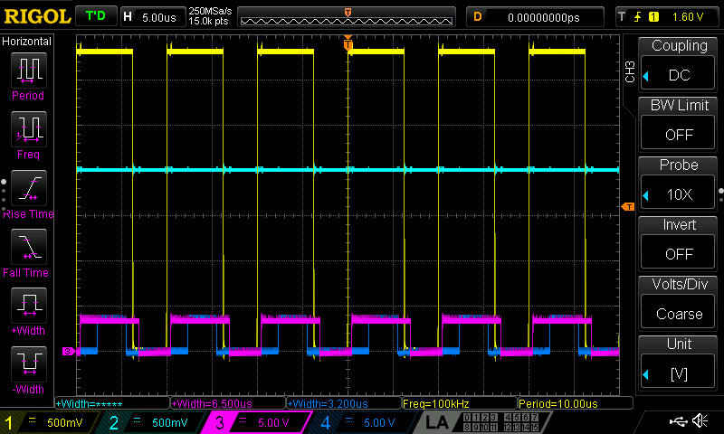
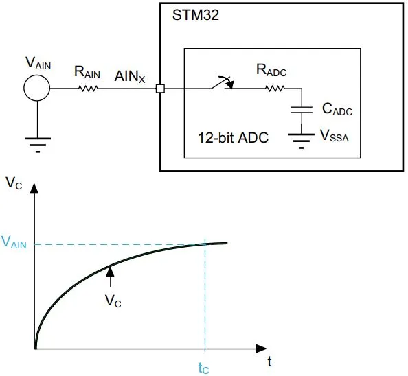
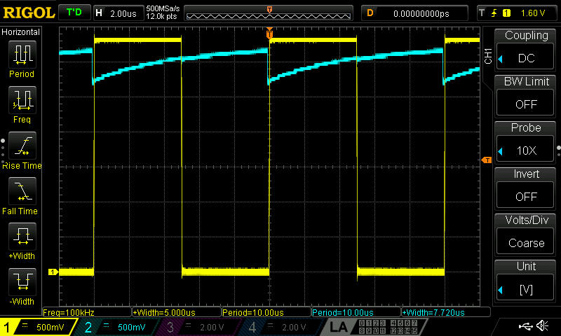
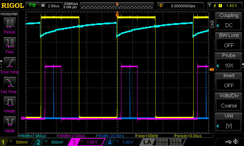
To check the "absolute" time where the ADC is converting, it may be needed to use a pullup resistor from a 3V3 source to the ADC pin. The 3V3 source could be another IO or Vcc itselft as shown below. It should be noted than when the switch of the ADC starts to close, the voltage will drop due to the internal capacitor charging.
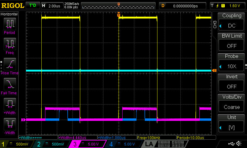
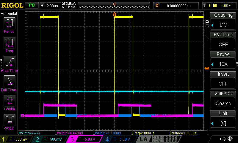
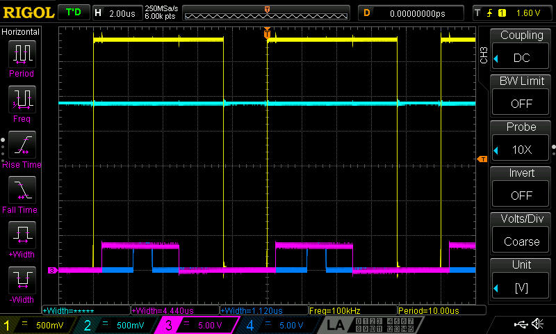
After adding this pull up resistor, check ADC pin waveform.
Need 2 I/Os to check the timing for ADC interrupt (if ever it goes inside it), 1 IO for ADC interrupt service routine (blocking mode) and 1 IO for ADC conversion "callback" (non-blocking mode).
ADC interrupt service routine
/**
  * @brief This function handles ADC1 and ADC2 interrupts.
  */
void ADC1_2_IRQHandler(void)
{
  /* USER CODE BEGIN ADC1_2_IRQn 0 */

	GPIOC->BSRR = (1 << 9); // Set

  /* USER CODE END ADC1_2_IRQn 0 */
  HAL_ADC_IRQHandler(&hadc2);
  /* USER CODE BEGIN ADC1_2_IRQn 1 */

  GPIOC->BSRR = (1 << 25); // Reset

  /* USER CODE END ADC1_2_IRQn 1 */
}
ADC conversion "callback"
/**
  * @brief  Injected conversion complete callback in non blocking mode
  * @param  hadc ADC handle
  * @retval None
  */
void HAL_ADCEx_InjectedConvCpltCallback(ADC_HandleTypeDef* hadc)
{
  /* Prevent unused argument(s) compilation warning */
  UNUSED(hadc);

  /* NOTE : This function Should not be modified, when the callback is needed,
			the HAL_ADCEx_InjectedConvCpltCallback could be implemented in the user file
  */

  GPIOB->BSRR = (1 << 8); // Set
  GPIOB->BSRR = (1 << 24); // Reset

}
CH1 = PWM Output
CH1 = ADC Pin
CH1 = ADC interrupt service routine
CH1 = ADC conversion "callback"
Check ADC value by debug mode. The value should be changing and almost same level as the voltage drop.
VoutMeasured = HAL_ADCEx_InjectedGetValue(&hadc2, ADC_INJECTED_RANK_1);
Now,it is known these facts from this experiment:
- Where exactly in time the ADC is acquiring and using a GPIO is not a good way to check where is that exactl location in time
- The interrupt is triggering
- ADC is acquiring and collecting correct data
- The Interrupt is within 10uS
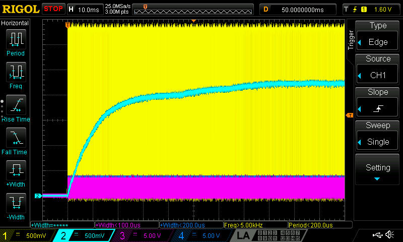
The Pull up resistor can now be replaced with the RC circuit intead of power devices.
Use the circuit as shown below.
Set different duty cycle and check the measured value, at initial setting of 50% duty, please remember that it is a 12-bit ADC and the full scale should be 4096.
pCompareCfg.CompareValue = 46080/2;
at 1/4 duty
pCompareCfg.CompareValue = 46080/4;
at 3/4 duty
pCompareCfg.CompareValue = (46080/4) * 3;
Notice above waveforms that CH3 and CH4 became wider because we started reading the ADC.
Also, there are some offsets from the calculated values, it could be one of the ff:
- The GPIO output is not really reaching 3.3V
- Constant offset is there
At this moment, offset is not an issue.
Set VoutTarget
volatile uint16_t VoutTarget = 2500; // haven't calculated what is the resulting Vout
Calculate PWM duty cycle by PID
errorProp = (Kp * Verror) >> 5;
errorIntgr = errorIntgr + ((Ki * Verror) >> 4);
errorDiff = Verror >> Kd;
pid_out =   errorProp + errorIntgr + errorDiff;
Set the PWM duty cycle to Comparator1
__HAL_HRTIM_SETCOMPARE(&hhrtim1, HRTIM_TIMERINDEX_TIMER_E, HRTIM_COMPAREUNIT_3, pid_out);
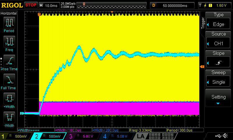
Even a simple RC network will exhibit a feedback oscilations depending on the PID formula.
Other PI formula (Using only Kp and Ki)
seterr = (-Kp * Verror) / 200;
Int_term_Buck = Int_term_Buck + ((-Ki * Verror) / 200);
pid_out = seterr + Int_term_Buck;
Start up
Normal Operation
Previous PID formula
errorProp = (Kp * Verror) >> 5;
errorIntgr = errorIntgr + ((Ki * Verror) >> 4);
errorDiff = Verror >> Kd;
pid_out =   errorProp + errorIntgr + errorDiff;
Start up
Normal Operation
That is just the start, it is up to the user to connect it to the power devices itself and add other features in the firmware. Also, it is up to the user what formula to use in its feedback control.
Using 3p3z in D-SMPS for feedback control, also using RC circuit
Fixed and Sliding ADC (youtube)
There has been numerous bugs in ST CubeMX when interrupt is enabled in HRTIMer Channel E, but the code generated is wrong. When you need to enable Timer update, pls modify as shown below.
from
pTimerCfg.InterruptRequests = HRTIM_MASTER_IT_NONE;
to
pTimerCfg.InterruptRequests = HRTIM_TIM_IT_UPD;
It is already reported in the ST Community...
VictorT Bug Report1 to ST
VictorT Bug Report2 to ST
VictorT Bug Report3 to ST
Disclaimer:
The projects posted here are for my Personal reference, learning and educational purposes only. The purpose of a certain project may be for testing a module and may be just a part of a whole project. It should not be used in a production or commercial environment. Any cause of injury and/or death is the sole responsibility of the user.

/RC-ckt.png)
