-
Notifications
You must be signed in to change notification settings - Fork 0
Home
UNDER CONSTRUCTION

Analog computers have a history of over 80 years and are still fascination in this modern times. Starting with 100000 DM in the past, the price drops to under 1000 € today. The projects goal is to offer a starter kit about 100 €.
The "Low-cost Anolog Breadboard Computer" - short LABC [ˈlæbˈsi] - is a open source / open hardware project to offer breadboard based development to hobbyists, pupils, FabLabs and hacker-spaces for education and fun.
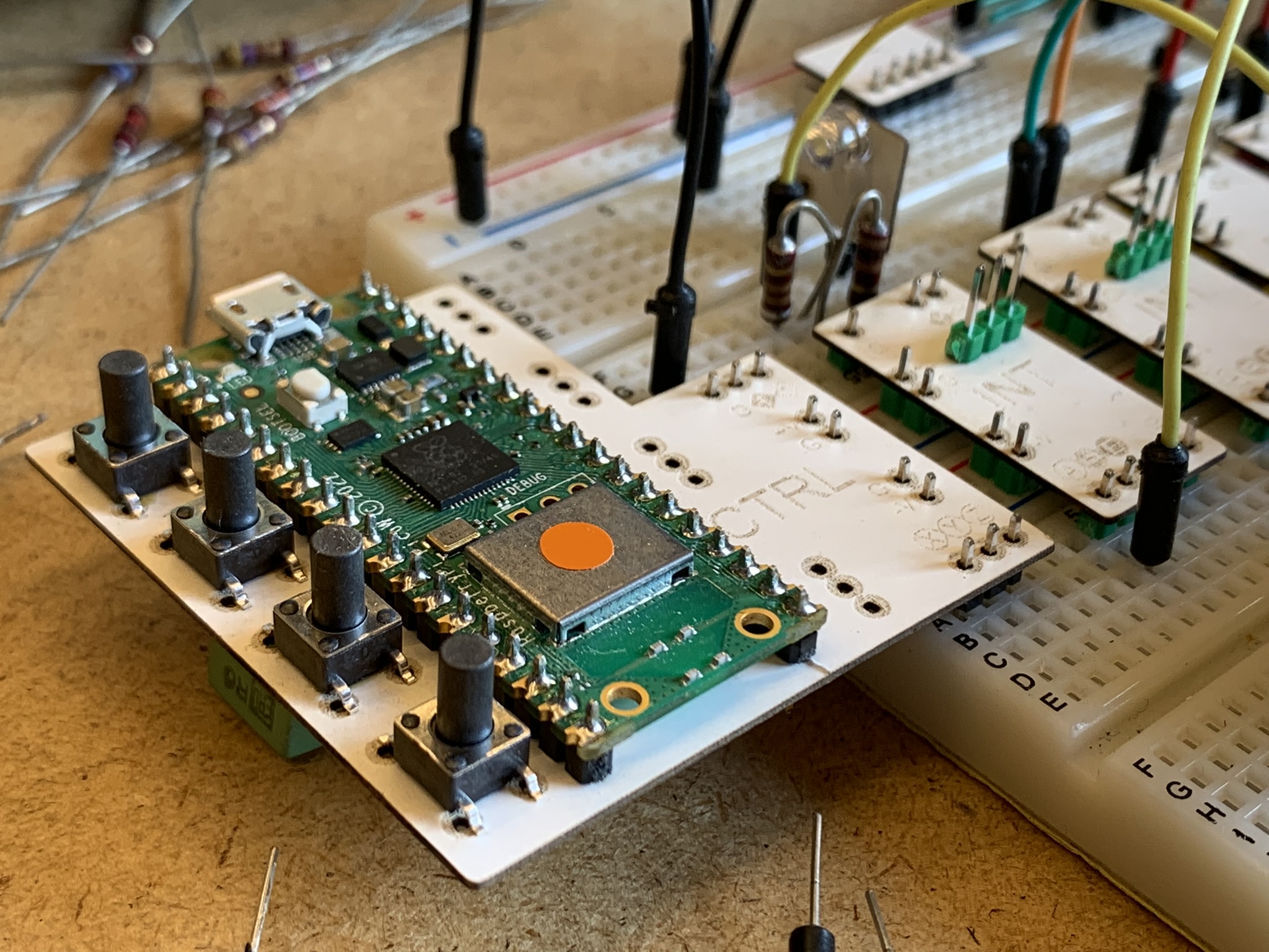
The breadboard is populated with singe purpose (adder, integrator, ...) tiny electronic boards (PCB) - the so called compute-modules. Each module is powered via its pin-headers and provides the inputs and outputs to the breadboard. The connection between the modules is done by jumper-wires on the breadboard.
By positioning the compute modules in data flow order (graphic layout) it is easier to follow the schematics and for most connections shorter cables (jumper-wires) can be used.
The control module provides all necessary voltages and hosts a Raspberry Pi Pico (W) for control, ADC and DAC. An USB-connection can provide a connected PC with measured data. This builds the bridge to simple hybrid computing.
Most standard breadboards come with two power-rails - one on top, one on bottom. This boards have clips to connect them together. For this project two (or more) standard breadboards are clipped together to get two power-rails (4 lines) in direct neighborhood. This rails supply the compute modules with +15 volt, -15 volt and a set-input for initial condition (SIC).
Note: Ready mounted breadboards on a base sheet/plate often have no two middle-rails and can not be used for this project.
Note: The standard breadboards are based on a 2.54 mm grid but the power-rails are displaced by 1/2 grid horizontally and 1/4 grid vertically.
The hole thing is powered by 5 volts over an USB connector on the control module. The USB cable can be plugged in a phone-charger, a PC or a power bank.
The control module hosts a filtered DC/DC-converter to get ±15 volts to feed the breadboards middle-rails.
Additional linear regulators provides ±10 volts for coefficients source and integrator start condition.
The middle-rails of the breadboard provides the ±15 volts for the operation-modules. All modules have 4 pins (pin-header) on the side to get the +15, -15 and 1x ground and SIC signal
The rails on upper and lower side of the breadboard provides regulated ±10 volts for ±1 reference (coefficients source and integrator start condition).
The OpAmps are connected to ±15 volts (with ground) from the power supply (control module). The operation voltage is ±10 volts which represents ±1 in equation. This voltage is also supported by the control module.
All operations are normalized to ±10 volts. E.g. the multiplier get ±10 volts as input and the result is also ±10 volts -> out = (a * b) / 10
All active Modules (adder, integrator, ...) provides an 'normal' output and an inverted output. So additional adder-modules as inverter can be saved/spared.
Best fit for displaying analog results over time or y over x is an analog oscilloscope. Old low end oscilloscopes can be found on eBay and garage sales for a very low price.
Digital oscilloscope are in principle also usable but because of their quantisation (rastering) the result is often inadequate.
Each Module is a tiny electronic board (PCB) which has only one purpose (e.g. adder, multiplier, integrator, ...).
Modules which needs voltage from power supply (±15 volts) are designed to fit in the 2.54mm-grid (1/10") as well as the displacement of the middle-rails.
Typically the inputs are placed on the lower side and the outputs and control pins are placed on the upper side. Additional ground pins can be added to plug in resistors as voltage dividers.
TODO

| Mod | Description |
|---|---|
| CTRL | Control Module |

TODO
maybe overshot Duo-LED in each module...
Note: Not all listed modules have to be implemented in 1st version
| Mod | Description |
|---|---|
| ADD | Adder/Summer |
| INT | Integrator |
| MUL | Multiplier |
| DIV | Divider (Future Option) |
| CMP | Comparator |
| ABS | Absolute/Rectifier |
| BUF | Buffer/Inverter |
Passive means not calculating function but helpful to support the program.
| Mod | Description |
|---|---|
| TRS | TRS-adapter |
| BNC | BNC-adapter |
| OVR | Overshot display |
| R5, R10 | Coefficients |
| SWx | Switches |
For a analog program many coefficients are needed. Some are constant, some need only a precision of ±5%, other need a very high precision. Using 10-turn-potentiometers for all coefficients is an overkill in cost and space.
The idea is to have individual/different tiny solutions for each individual coefficient. This coefficient-modules or -components can be placed near the compute-modules on the breadboard to get a graphical layout and minimal cable length.
A normal potentiometer (poti) with 10kOhm lin. - as is - is used.
With no buffer the error in middle position is about 0.1% for following 'normal' inputs (x1) and about 1% or following 'scaled' inputs (x10). If a higher precision is needed, a buffer-module can be added to the breadboard.
The advantage is, that the poti can be placed at any position on the breadboard with only an additional cable to GND.
If the poti has a thread, a scale panel can be added to get a rough feeling of the coefficient.
The user can use normal wired resistors (THD) to build any constant divider. The Rs can be plugged nearby the compute modules at their inputs or outputs on the breadboard.
10-turn-potentiometers with 1% scale display...
3D-printed housing recommended...
Using one or two BCD-switches with scaled resistors an numeric input (0...99) can be build.
Application note follows...
TODO
