-
Notifications
You must be signed in to change notification settings - Fork 38
Compatible boards
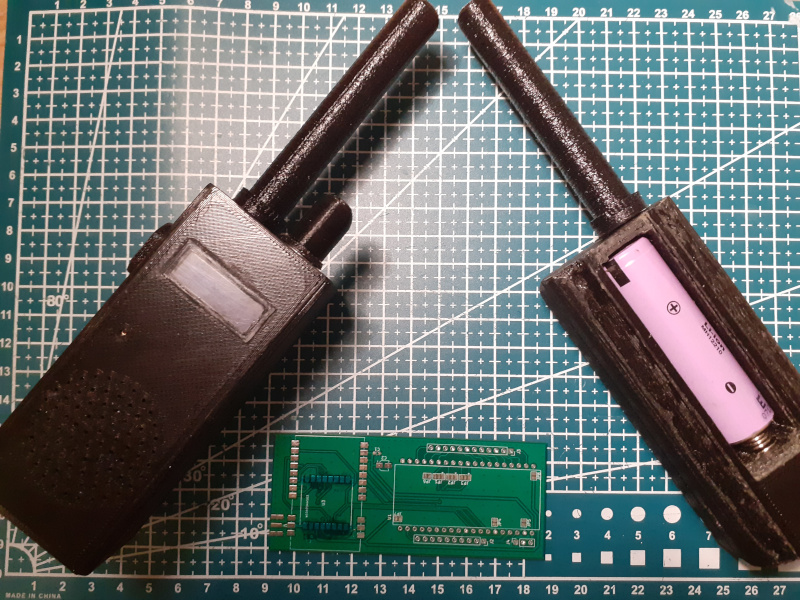
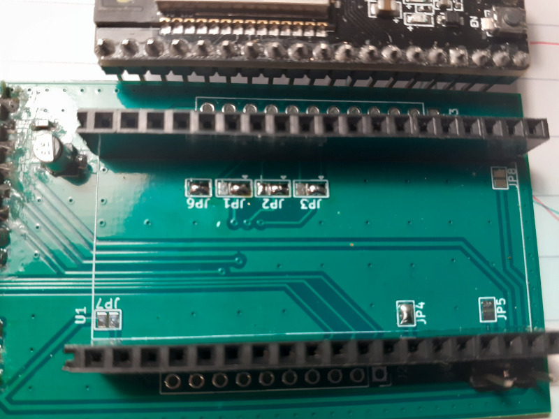
All work was done on ESP32-WROOM with custom made dual module RA-01/SX1278, E22-400M30S/SX1268 LoRa board.
Arduino Board is "ESP32 Dev Module".
Prototype development board schematics is available at https://github.com/sh123/lora_tracker.


If using RadioLib then supported modules - modules, which are supported by RadioLib:
-
SX1278 is a default module, for other
SX127xmodules need to updateconfig.h, replaceMODULE_NAMEwith your module name according to RadioLib naming -
SX1268 is used when
USE_SX126Xis enabled inconfig.h, for otherSX126xmodules need to set correspondingMODULE_NAMEinconfig.h - other RadioLib module types - check RadioLib documentation, modify
config.hand code accordingly, open Issue if help is needed, most likely it will not compile out of the box and some changes are needed.
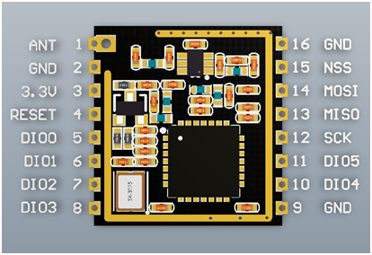
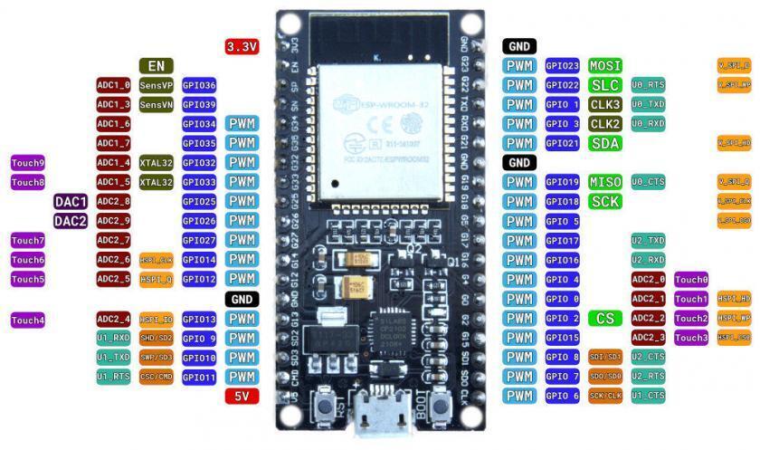
If your ESP32 board is compatible or has build in LoRa module then it should work without redefining pinouts, for custom shields there might be need to redefine pinouts to LoRa module if it differs (see further description in Software Setup section), currently pinouts are connected from LoRa to ESP32-WROOM as (SS/RST/DIO0 could be redefined in config.h):

- Common SPI:
- MOSI: GPIO_23/VSPI_MOSI
- MISO: GPIO_19/VSPI_MISO
- SCK: GPIO_18/VSPI_SCK
- Board specific:
- SS/CS/NSS: GPIO_5
- RST/RESET: GPIO_26
- DIO0/IRQ: GPIO_14
![]()
Supported (built-in screen is not used), just select board in Arduino IDE->Tools->Board, no need to redefine pinouts:
- T-Beam LoRa
- LoPy, LoPy4
- TTGO LoRa32 v1
Require LoRa module pinout definitions in config.h:
-
Heltec WiFi LoRa 32 (v2), redefine pinouts as
#define LORA_RST              14
#define LORA_IRQ              26
- ESP-WROOM32 38pin


Pinout definitions:
#define CFG_LORA_PIN_RST      26
#define CFG_LORA_PIN_A        12
#define CFG_LORA_PIN_B        14
#define CFG_LORA_PIN_RXEN     32
#define CFG_LORA_PIN_TXEN     33