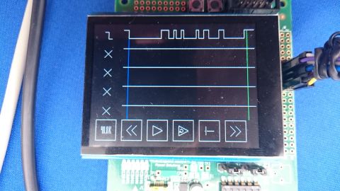
Pocket Logic Analyzer for MAX 10 FPGA and Adafruit Arduino TFT
This project implements a simple hand-held logic analyzer with 5 channels, selectable clock (external, or internal up to 50MHz), various trigger conditions, all controllable via touch screen. It still needs some more features and polishing before it's really usable as a debugging tool, but in its current state it's still fun to play with.
It uses this board with this screen. The capacitive touch interface uses the I2C pins which are not pinned out on the MAX 10 board by default, so I may need to provide some diagrams showing how to solder that up later. I currently have scl on PIN_88 and sda on PIN_90.
Low-level code to interface with the display and touch interface is distributed via the MIT license.
Some Documentation:
- Adafruit Guide
- ILI9341 Specification
- FT6x06 Datasheet
- FT6x06 Application Note
- Opencores I2C-Master Core Specification
You can compile the design using Quartus Prime Lite Edition (Previously known as Quartus II Web Edition). I'm going to try to avoid proprietary components so it may be ported easily to other boards and other FPGA manufacturers. Notably, I am not going to use a NIOS II microcontroller for the main program logic. Instead everything will be HDL. This may also be because I'm a mashochist.
This particular MAX 10 board was chosen because of the Arduino header, but it doesn't have an on-board USB Blaster. To program you can use any generic JTAG programmer, or a USB-Blaster clone, or even a real USB Blaster if you have one. I used this and it worked fine. More detailed instructions on how to program will come in the future.
