This guide will help you create a piece of parametric design.
Check out one of the designs from our gallery to see what that looks like.
You can read more about the project here.
It assumes you have an understanding of Javascript, Git (basics) and ThreeJS. (It's good enough if you have just about worked with them once).
Let's get started.
Get the starter project by cloning https://github.com/O-LAP/starter_project.git.
The starter_project has files in place to let you run and test your design in a development environment and once you push it and register it with the main app, it runs smoothly with the framework as well.
The starter project is configured to show a simple cube which can be controlled using parameters in the browser.
This exercise will replace that cube with our own design.
You can open up the dev.html file in a browser to see what currently it looks like.
It should be something like this.
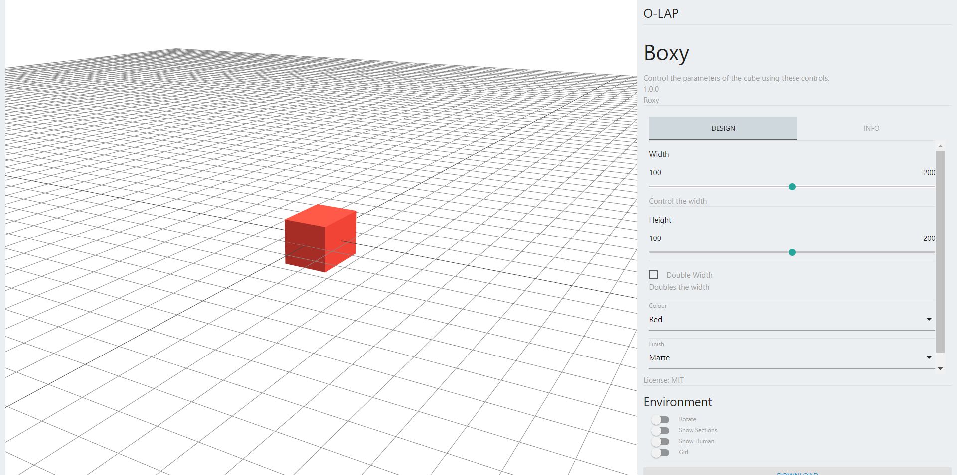
You can change the sliders on the right hand side which change the dimensions of the cube.
You will see a group of controls under 'Environment' on the bottom right.
Try enabling the 'Show Section' switch. It shows sections of the cube which can be fabricated.
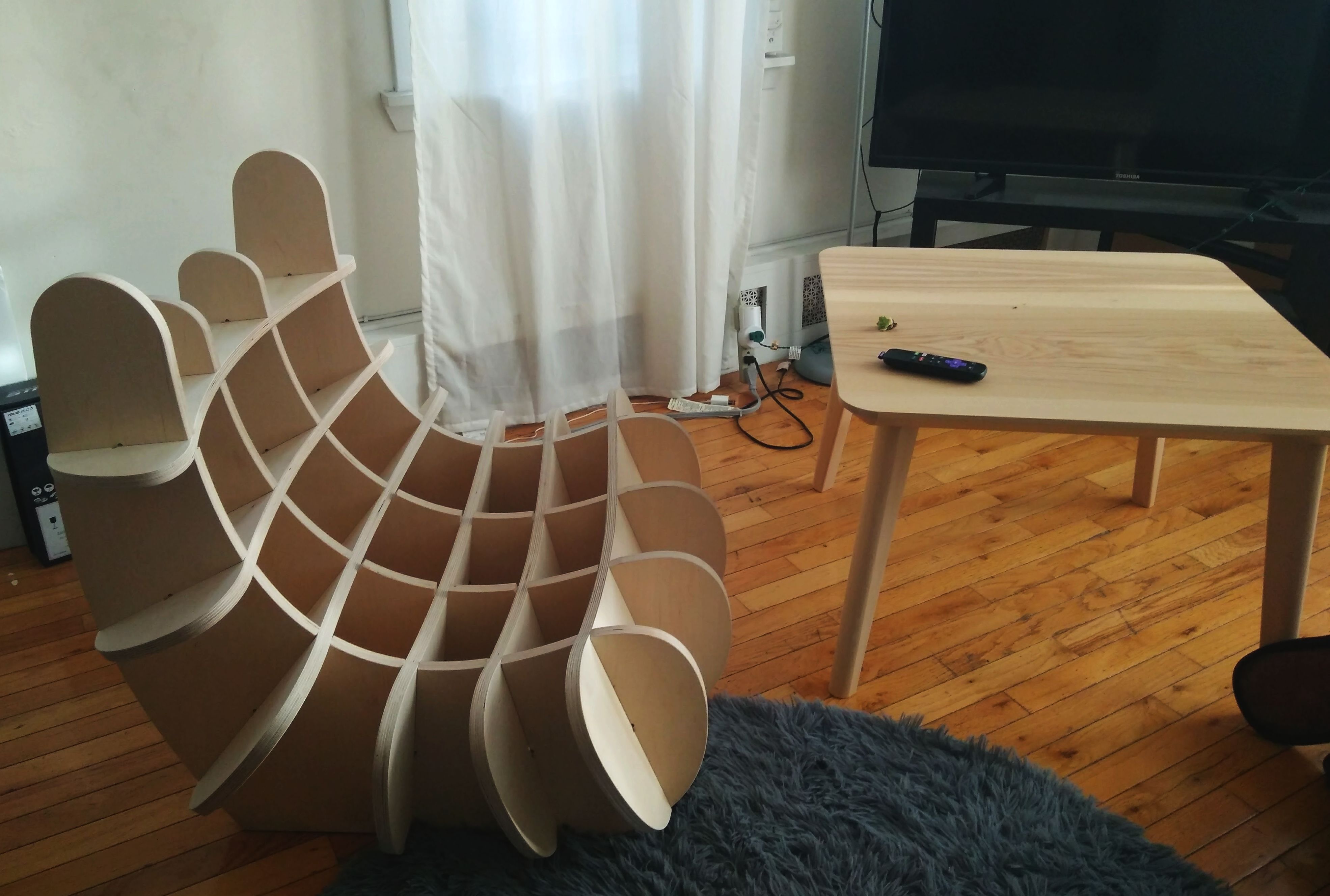
We can use those sections to make the cube with real wood.
When you click the 'Download' button, the app gives you a CAD file(.obj) which you can feed into a CNC machine to get it fabricated.
You can read more about this process here.
This a sample of a chair made using this technique.
Let's start by making a parametric cylinder (which you can imagine as a small stool) replacing the cube.
The designs folder contains all the files you need for the design.
The Design.js file contains some sample code showing a cube which can parametrically modified.
The dev.html file is the development harness which emulates the OLAP web app.
The framework requires the design logic to be captured in a Javascript object called Design in Design.js file.
Design.info = { ... };
Design.inputs = { ... };
Design.inputState = { ... };
Design.init = async function() { ... };
Design.updateGeom = async function(group, sliceManager) { ... };
Design.inputs is where you specify the parameters for your design.
It is configured for the cube.
Let's modify it to make it suitable for our sphere.
We will keep things very simple and only use height and weight for our cylinder.
Update Design.inputs so it looks like this.
Design.inputs = {
    "width": {
        "type": "slider",
        "label": "Width",
        "default": 150,
        "min": 100,
        "max": 200
    },
    "height": {
        "type": "slider",
        "label": "Height",
        "default": 150,
        "min": 100,
        "max": 200
    }
}
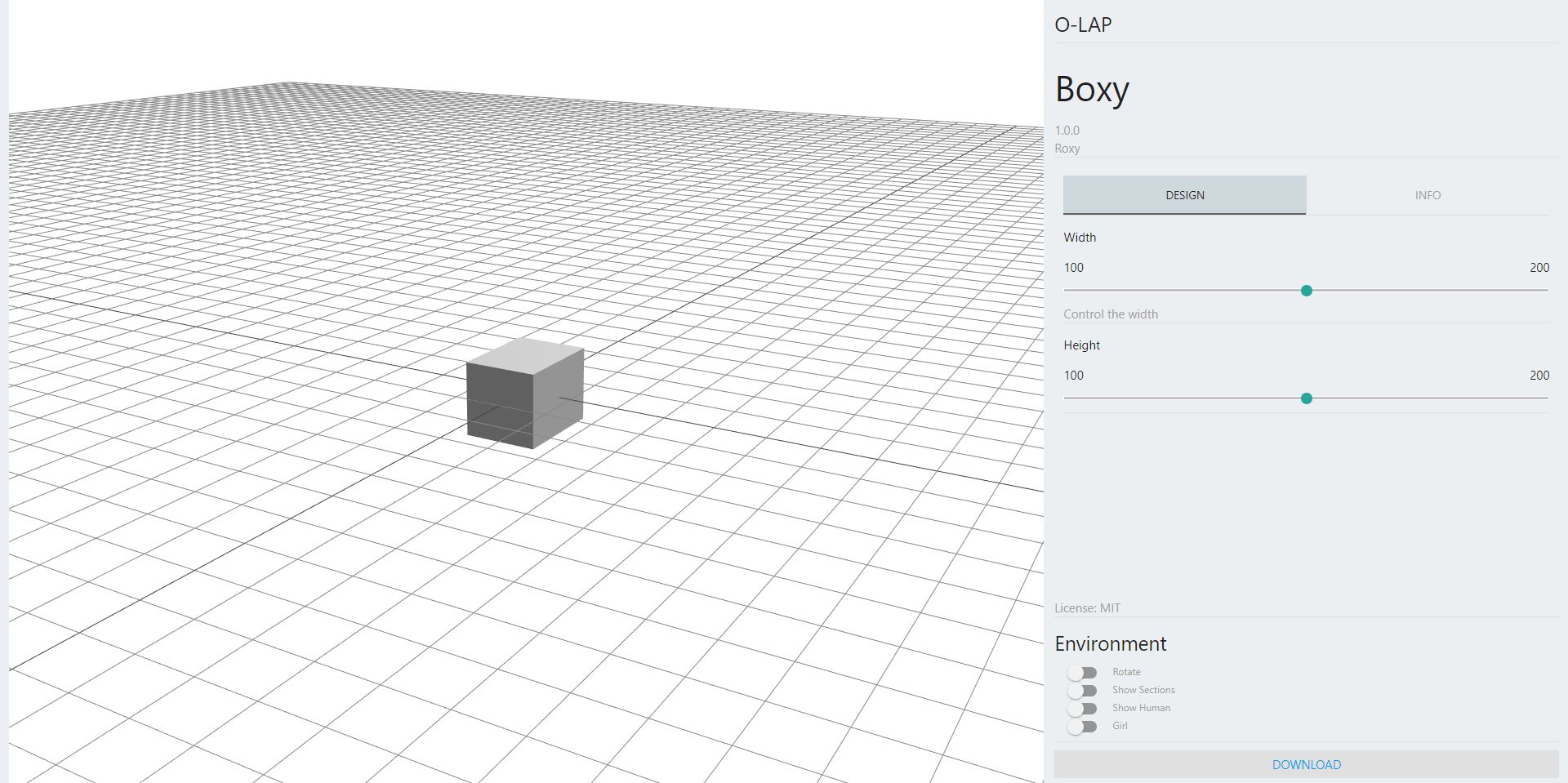
Now if you open dev.html it should look something like.
Now we will create a cylinder instead of a cube.
The design is updated everytime a parameter value is changed and on initital load.
It passes in an empty THREE.Object3D which is the container for you to add geometries to and a SliceManager which the you can use to specify how to make the 'slices' for the design. References from the previous update call are discarded and fresh instances for every call are used.
Design.updateGeom = async function(group, sliceManager) { ... };
Let us look at what the updateGeometry method looks like for the cube.
Design.updateGeom = async function(group, sliceManager) {
  var geometry = new THREE.BoxGeometry( 200, Design.inputState.height, Design.inputState.width * ((Design.inputState.doubleWidth) ? 2 : 1) );
  var material = getMaterial(Design.inputState.colour, Design.inputState.finish);
  var cube = new THREE.Mesh( geometry, material );

  sliceManager.addSliceSet({uDir: true, start: -80, end: 80, cuts: 3});
  sliceManager.addSliceSet({uDir: false, start: -90, end: 90, cuts: 4});

  group.add( cube );
}
You can use Design.inputState to access the current value set by the user for the parameters at all times. For eg.
To access the value for height parameter you can use Design.inputState.height.
The first 4 lines are pure threeJS code, where it creates a simple BoxGeometry based on the parameter values.
This is the main part of your design which you will modify in the following step to create a design using the parameter values.
The part after that with the sliceManagers manage how the section profiles are created for your design.
More information about slicing further below.
We will modify this method so it ends up looking like this.
Design.updateGeom = function(group, sliceManager) {
  var geometry = new THREE.CylinderGeometry( Design.inputState.width -100, Design.inputState.width, Design.inputState.height, 32 );
  var material = new THREE.MeshStandardMaterial( {color: 0x00BFFF } );
  var cylinder = new THREE.Mesh( geometry, material );

  sliceManager.addSliceSet({uDir: true, start: -80, end: 80, cuts: 3});
  sliceManager.addSliceSet({uDir: false, start: -90, end: 90, cuts: 4});

  group.add( cylinder );
}
We replace the 3 lines which created the cube with 3 lines which create a cylinder.
We use the width and height from the design parameters and a fixed color.
We retain the same slicing settings as before and update the last line to add the cylinder instead of the cube.
Hit save and try refreshing the page to see the change.
You should see something like this.
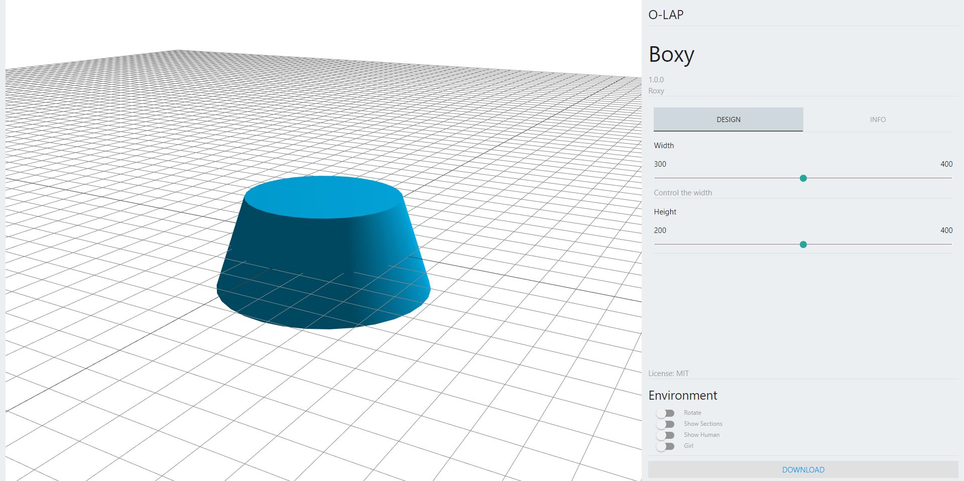
Trying playing with the parameters and check how the sections look like for this design.
You can work with any threeJS mesh to define the geometry of your design.
All geometry passed into the group is 'sliced' by the slicing configuration as per supplied settings.
This quick walk through demonstrated how you can parmetrically design basic geometries.
You can adapt this logic to create any kind of geometry which can be fabricated to furniture.
Check out this article to understand the use of computational techniques for furniture design.
Once you have a design you are happy with you can progress to submitting your design.
For this quick start we will submit our design to a test gallery we maintain.
All designs registered in the test gallery is periodically cleared.
Designs will be accepted into the main/test repo via pull requests. This will allow for a meaningful discussion in the add publish process.
Go to https://github.com/O-LAP/home/edit/master/data/TEST_DesignCollection.js.
If it is your first time adding a design you will be requested to fork the repo. Do it.
Add the link to your repository (eg https://github.com/amitlzkpa/o-lap_plato) to the list inside TEST_DesignCollection (check you have the commas at the right place).
Please make only one change at a time. Any proposals with more than one change will be rejected even if everything else is in place.
Click to propose the change. It will be moderated by one of the maintainers and if any further discussion is required it would happen via this page.
If accepted you can check your design by going to the link: http://o-lap.org/test.html?a=<github-user-name>&r=<olap-repo-name>
Most submittals to the test repo will be accepted.
As a community we hope the same process will be used to moderate designs which fail the requirements.
Submission Link (Main): https://github.com/O-LAP/home/edit/master/data/OLAP_DesignCollection.js
Submission Link (Test): https://github.com/O-LAP/home/edit/master/data/TEST_DesignCollection.js
Design Gallery (Main): https://O-LAP.github.io/home/designs.html
Design Gallery (Test): https://O-LAP.github.io/home/test.html
App: http://o-lap.org/app.html?a=<github-user-name>&r=<olap-repo-name>&m=test
Make updates to the design file.
You don't have to update your file at the same time. In fact its better to make your changes in small steps as seperate commits. With each commit include a meaningful description of what, how and why you made the changes.
Update the Design.js file to make only the version update change.
Modify the version number in at "version": "x.y.z",(line 11) inside Design.js
x.y.z (x: major changes; y: minor changes; z: tweaks) (more details)[https://semver.org/]
Start command line to your work folder. Run git clone <repo you want to fork>.
Open Design.js and make your changes.
You might want to rename the folder to whatever you would like to name your design.
After you are done making changes, reset the design version to 1.0.0 by modifying "version": "x.y.z", (line 11) inside Design.js
Update other information like name, short_desc, long_desc, message etc.
Start thinking of this design as a new design from now on.
If you want to continue pulling changes from the parent repo follow (page)[https://gist.github.com/CristinaSolana/1885435].
Submit your forked design as a new design by following the Submit Your Design process.
You are set!
We quicly glanced over a few things.
Now since you have a better understanding we will quickly look some more things.
At the top you will see the design meta information which looks like this.
Design.info = {
  "name": "Boxy",
  "designer": "Roxy",
  "version": "1.0.0",
  "license": "MIT",
  "short_desc": "Template design file demoing project setup.",
  "long_desc": "",
  "url": null,
  "message": "Control the parameters of the cube using these controls.",
  "tags": [ "", "" ]
}
This is used to show information about the design on the gallery.
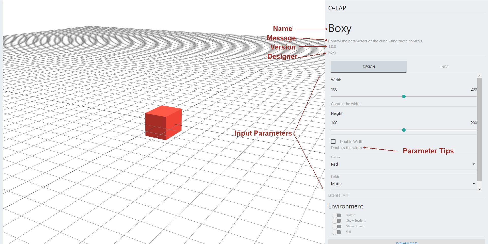
To give you control over your input parameters, you can specify different types of input.
Design.inputs = { ... };
There are 4 types of paramaters you can provide - slider, bool, select and text.
slider is used to allow the user to pick a numercial value from a continuous range. The values are in integers.
bool allows the user to pick from a yes/no value.
select allows the user to select one from a list of values.
text takes input for text values.
To add a parameters to your design you need to register it by adding a key-value pair to Design.input.
Slicing is the process of extracting straight sections from your design which we can us to fabricate the design.
Read the faq to understand the process.
Use the sliceManager to communicate to the framework how you want the design to be sliced.
We do this by passing a config object to the SliceManager.
If we want to create slices along the X-axis at -80 and go up +80 with 3 slices equally distributed in that range. (All distances are in millimetres), we pass in an object that looks like this.
{uDir: true, start: -80, end: 80, cuts: 3}
To create another set of slices along the Y-axis which start at -90 and go up to +90 with 4 cuts, we pass in an object like this.
{uDir: true, start: -90, end: 90, cuts: 4}
Make sure to specify the slicing configuration right before adding the geometry.
Generally, with two sets of slices in the opposite directions you should have designs which can be fabricated.
But you need to be careful about how you think of this in your design.
Read the design guidelines to get a better understanding of this.
This guide walked you through the steps involved in getting the right files, making a design from scratch and submitting it.
To understand more about parametric furniture design check out the design article.
Experiment with the concept and its creative potential (constrained to the physical production limitations).
To submit designs to the main gallery make sure to read the design guidelines.
If you are interested in learning how the framework works and more general documentations, read the faq.