This is a tasmota setting guide of MCP230XX (MCP23017 and MCP23008) and also integrate into HomeAssistant
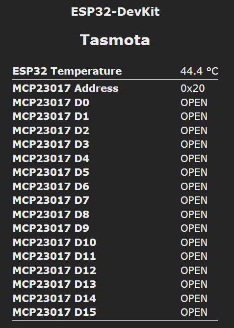
- This script provides a web interface to show the status of the MCP230XX I2C GPIO expander.
- It's aimed to be used the MCP230XX I2C GPIO expander with
input mode(so it can be used to read the status of the input pins). - After that, the device can work with 8 or 16
reed switches,PIR sensors,motion sensor, etc.
- You need to install a tasmota firmware that supports the MCP230XX I2C GPIO expander.
- For example, install the
Tasmota All Sensors (english)firmware by using Install Tasmota website.
- Please refer to the Tasmota documentation MCP23008 / MCP23017 GPIO Expander for the hardware connections
- In this guide we will use the MCP230XX I2C GPIO expander with the following connections:
- MCP230XX SDA: GPIO4
- MCP230XX SCL: GPIO5
- MCP230XX Address: 0x20
- MCP230XX tasmota mode: Mode 1
- Go to
Configuration->Configure Modulepage and selectI2C SDAandI2C SCLpins for the MCP230XX I2C GPIO expander. - Go to
Tools->Consolesand enter the following commands:
I2Cscan: Check if the MCP230XX I2C GPIO expander is detected (0x20)Sensor29 Reset2: Set the MCP230XX I2C GPIO expander toinput mode with pull-upSetOption59 1: Set extra SENSOR status telemetry messages (for HomeAssistnat)
- You should see the console output similar to the following:
stat/tasmota/RESULT = {"Sensor29_D99":{"MODE":2,"PULL_UP":"ON","INT_MODE":"ALL","STATE":""}} - Go to
Configuration->Manage File systemand upload theMCP230XX_WebUI.bescript. Make sure the file is uploaded successfully. - Also in the
Manage File system, add the following line intoautoexec.befile (If you don't have this file, create it):
load('MCP23017_WebUI.be')
- Reboot the device and you should see the MCP230XX I2C GPIO expander status in the web interface.

- If you want to change the state text such as
ON/OFForOPEN/CLOSE, you can change the linevar state_text = {-1:"NULL", 0:"CLOSE", 1:"OPEN"}inMCP23017_WebUI.be
SetOption146 1: Enable display of ESP32 internal temperatureWifiConfig2: Set Wi-Fi Manager as the current configuration tool
- You should install the
Mosquitto brokeradd-on in HomeAssistant. - For the Tasmota device, go to
Configuration->Configure MQTTand complete the following fields and save the configuration:
Broker: IP address of the HomeAssistantPort: 1883Username: Your HomeAssistant MQTT usernamePassword: Your HomeAssistant MQTT password (Remember to check the Password box)
- Back to HomeAssistant, go to
Configuration->Integrationsand add theMQTTandTasmotaintegration. - The Tasmota device should be detected by HomeAssistant automatically.
- In HomeAssistant, go to
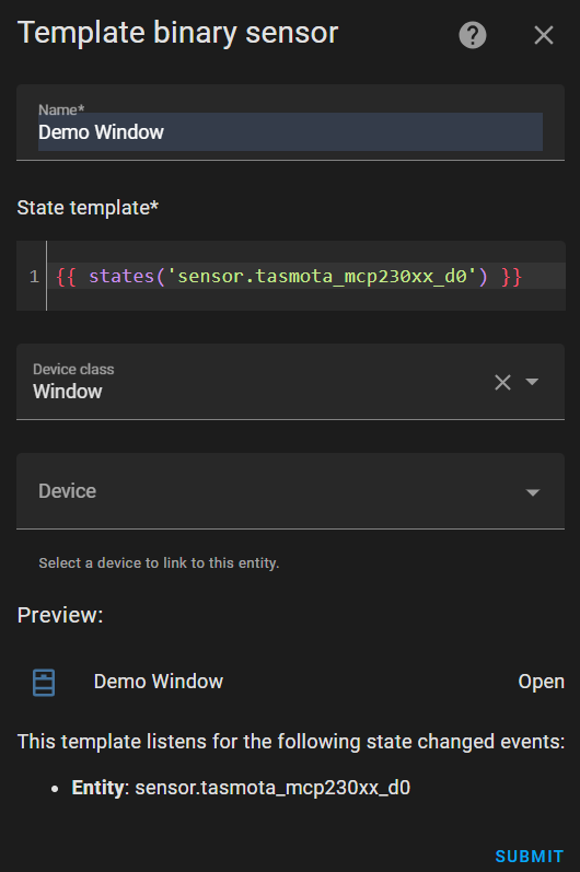
Device and Services->Helpers->CREATE HELPER->Template->Template a binary sensor - Enter the following settings:
- Name: Your sensor name (e.g.
Demo Window) - State template:
{{ states('sensor.tasmota_mcp230xx_d0') }}(Change thed0tod0~d15depends) - Device class:
Window(depends on your sensor type) - Then click
SUBMIT
- You can see the sensor status in the HomeAssistant.